Steel Doors and Ventilators and Composite Units
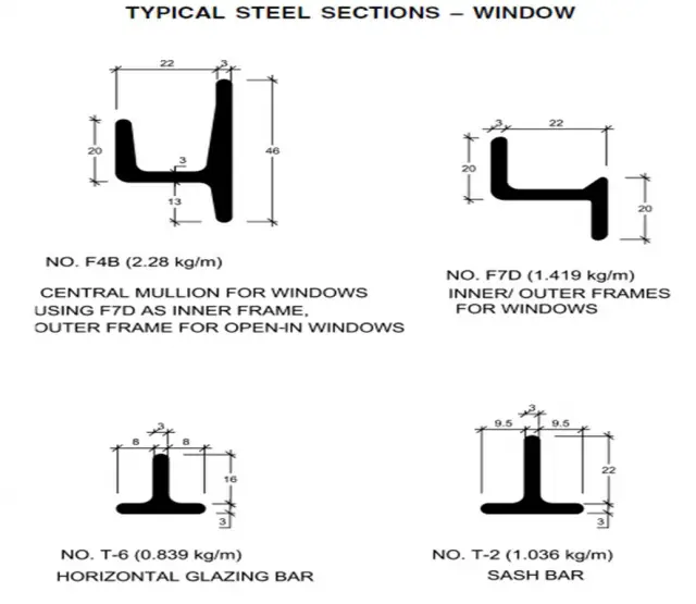
- Shall be manufactured using rolled steel sections of the weights specified
- It shall be fixed center hung top hung bottom hung or composite as specified .the steel shall be of S.T.32 0 grade
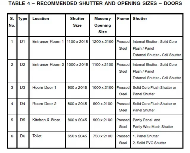
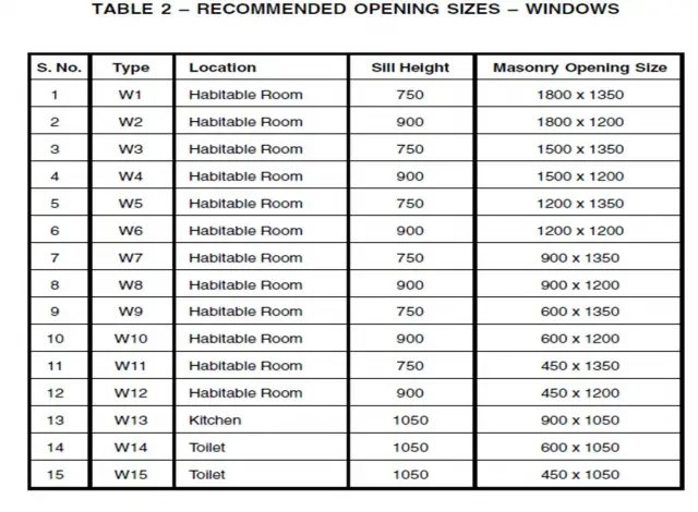
SIZE
- The type, overall sizes, side opening, position of steel doors windows and ventilators shall be as per detail given by engineer-in-charge.
- The provision of threshold or of the tie bar at the bottom of the door shall be specified (usually external doors shall be provided with threshold and internal doors with tie bars etc)
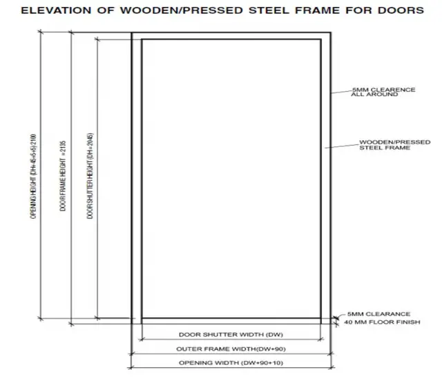
- The steel doors and windows shall be according to the specified sizes and design .the sizes of doors and windows shall be calculated so as to allow 1.25 cms. clearance on all the four sides of openings to allow for any fitting of doors, windows and ventilators into opening. The actual sizes of doors windows and ventilators shall not vary by more than 1.5mm from those given in the drawing.
HANDLES
- The handle shall have a two-point nose which shall engage with the brass striking plate on the fixed frame in a slightly open position as well as in the closed position.
- The boss of the handle shall incorporate a friction device to prevent the handle from dropping under its own weight and the assemble shall be so designed that the rotation of the handle may not cause it to unscrew from the pin. The strike plate shall be so designed and fixed in such a position in relation to the handle that with a later bearing against its stop, there shall be adequate tight fit between the casement and outer frame.
- In case where non-friction type hinges are provided the window shall be fitted with peg stays which shall be either of black oxidized steel or as specified, 300mm long with steel peg and locking brackets, stays shall have three holes to open the side hung casement in three different angles.
- Side hung casement fitted with friction hinges shall not be provided with a peg stay.
- Specified side hung shutters may be fitted with an internal removable fly-proof screen in a 1.25mm thick sheet steel frame applied to the outer frame of the shutter by brass turned buckles at the jambs and brass studs at the sill to allow the screen being readily removed. The windows with removable fly-proof screen shall be fitted with a through the screen level operator at the sill to permit the operation of the shutter through an angle of 90 degree without having to remove the fly-proof screen. The lever shall permit keeping the shutter open in minimum 3 positions.
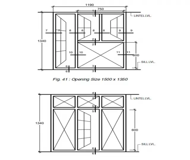
RECOMMENDED ELEVATION OF WINDOWS FOR FIXING COOLER/AC
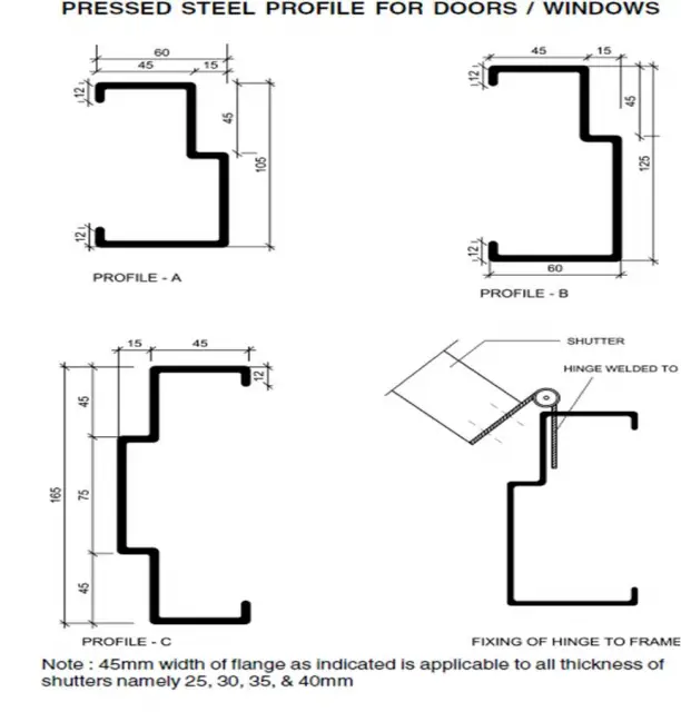
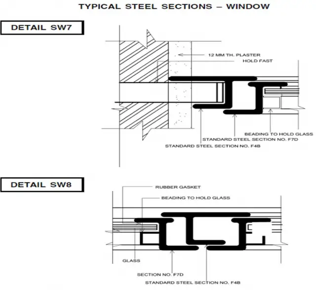
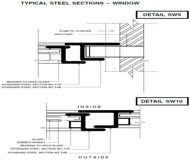
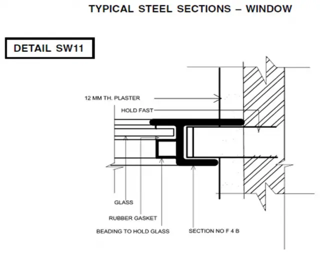
FABRICATION
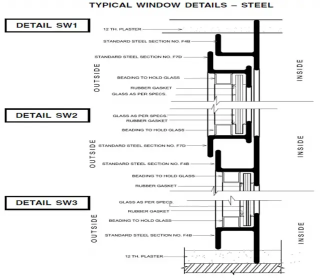
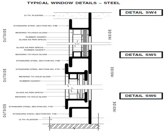
- Frames – both the fixed and opening frames shall be constructed of sections which have been cut to length and mitered.
- The corners of fixed and opening frames shall be welded to form a solid fused welded joint conforming to the requirements.
- All frames shall be square and flat.
- The process of welding adopted may be flash butt welding or any other suitable method which gives the desired requirements.
SIZE
- The type , overall sizes, side opening, position of steel doors windows and ventilators shall be as per detail given by engineer-in-charge.
- The provision of threshold or of the tie bar at the bottom of the door shall be specified (usually external doors shall be provided with threshold and internal doors with tie bars etc)
Steel Doors and Ventilators and Composite Units
- Shall be manufactured using rolled steel sections of the weights specified. It shall be fixed center hung top hung bottom hung or composite as specified .the steel shall be of S.T.32 0 grade
- SIZE – the type, overall sizes, side opening, position of steel doors windows and ventilators shall be as per detail given by engineer-in-charge. The provision of threshold or of the tie bar at the bottom of the door shall be specified (usually external doors shall be provided with threshold and internal doors with tie bars etc)
- The steel doors and windows shall be according to the specified sizes and design. The sizes of doors and windows shall be calculated so as to allow 1.25 cms clearance on all the four sides of openings to allow for any fitting of doors, windows and ventilators into opening. The actual sizes of doors windows and ventilators shall not vary by more than 1.5mm from those given in the drawing.
Windows
HINGES
- For fixed windows, the frame shall be fabricated as specified.
- Side hung window – for fixing steel hinges, slot shall be cut in the fixed frame and hinges inserted inside and welded to the frame. The hinges shall be of projecting type and not less than 65mm and not more than 25mm wide. The hinge pin shall be of galvanized steel.
- For fixing hinges to inside frame, the method described above may be adopted but the weld shall be cleaned or holes made in the inside frame and hinge riveted.
- Friction hinges shall be provided for side-hung windows, shutters, as specified. The casement window fastener for side hung shutters shall be of black oxidized steel or as specified and mounted on a steel plate. The handle plate shall be welded, screwed or riveted to the opening frame in such a manner that it should be fixed before the shutter is glazed and should not be easily removable after glazing.
PRECAUTIONS
- Care shall be taken that steel doors and windows etc are not deformed, damaged during subsequent construction. Particular care shall be taken that scaffolding does not rest on the steel door and window frames or glazing bars. All footings and hinges (projecting hinges) shall be protected, preferably with alkathene sheets, so that these may not be damaged during execution of work.
MEASUREMENTS
- The height and width shall be measured correct to 1mm. The area shall be calculated in square meters correct to two places of decimal. The fixed, side-hung and top-hung categories shall be taken separately.
- All composite units shall first be measured as fixed. Extras shall then be added for side-hung, top-hung and center-hung portions. The measurements for extra for side-hung, center-hung and top-hung windows shall be measured from outside to outside of the casement frames.
RATES
- Rates shall include the cost of materials and labor involved in all the operations described above excluding two coats of painting and including cost of glazing and priming including the one of projecting hinges in case of side-hung doors, windows, plain hinges in case of top, bottom hung windows, ventilators and pivots for center-hung windows/ventilators.
- Metal beading and other fittings such as peg stays and casement window fasteners etc shall be enumerated and paid for separately.
FIXING
The different methods are:
- Fixing with lugs
- Fixing with screws and plugs
- Fixing in woodwork openings
- Fixing in steelwork openings
Fixing with steel work openings:
- Before placing the unit frame in position approved mastic shall be applied as specified and a mild steel or hard wood fillet shall be provided around the frame to close the extra gap between opening and frame. The unit shall then be fixed to the opening with fixing clips or with nuts and bolts as showing in drawings or as directed by the engineer in charge.
Fixing with wood work openings:
- Openings in wood work are normally rebated and approved mastic or rubber linings shall be applied to jambs, sill and channel before fixing in position. The frame shall be set in opening using wooden wedges as specified and fixed to the opening with 60 mm galvanized wood screws of designation 10. Extra timber fillets of hardwood to match the adjoining work shall also be provided around the frame to close the extra gap between opening and frame.
Fixing with screws and plugs:
- In RCC work, where lugs cannot be embedded due to reinforcement bars etc., rawl plugs or other approved of metallic fasteners may be fixed in proper position and frames fixed to them with 60mm galvanized wood screws of designation 10.
Fixing with lugs:
- Doors, windows and ventilator units shall not be ‘built-in’ as the work proceeds but openings shall be left out and frames fitted afterwards so that the minimum specified clearance between opening unit and frame is left all around. The size of the opening shall first be checked and cleared of obstructions if any. The position of the unit and fixing holes shall be marked on that jamb. The necessary holes shall be made in the masonry and lugs not less than 10cm long 15x3mm size fixed in cement concrete blocks 15x10x10cm size of 1:3:6 mix (1 cement: 3 coarse sand: 6 graded stone aggregate 20 mm nominal size). The frames of units shall be set in the opening by using wooden wedges at the jamb, head and sill, (wedges shall preferably be placed near the points where a glazing bar meets the frames and be plumbed in position).
- After it, the frame shall be fixed with the lugs with 20 mm long and 6.3mm dia. GI counter sunk machine screws and nuts. In case of flush opening which are rendered smooth, wedges shall be removed and gap between unit and the jambs shall be filled with cement mortar.
- In case of flush jamb with external ‘fair-faced’ finished the gap between the opening and frame shall be filled with mastic from inside till it oozes out on external face. The oozing mastic shall be cleaned and flush-pointed. The internal gap shall be filled with mastic to about 1/3 depth and the rest with cement mortar.
- In case of rebated jambs and jambs finished ‘fair-faced’ externally, the mastic shall be freely applied to the inside channel of frame, jamb and sill, so as to ensure a water-tight joint. After the unit is firmly fixed in position, surplus mastic shall be cleaned and flush-pointed.
Leave a Reply
You must be logged in to post a comment.