
TAIPEI 101 – A structural marvel created by combining the best of all structural systems.
SOME BASIC INFORMATION
- Architect – C.Y.Lee & Partners
- Structural Engineer – Shaw Shieh
- Structural Consult. – Thornton-Tomasetti Engineers, New York City
- Year Started – June 1998 (Mall already open)
- Total Height – 508m
- No. of Floors – 101
- Plan Area – 50m X 50m
- Cost – $ 700 million
- Building Use – Office Complex + Mall
- Parking – 83,000 m2, 1800 cars
- Retail – Taipei 101 Mall (77,033 m2)
- Offices – Taiwan Stock Exchange (198,347 m2)
ARCHITECTURAL STYLE
- Structure depicts a bamboo stalk
- Youth and Longevity
- Everlasting Strength
- Pagoda Style
- Eight prominent sections
- Chinese lucky number “8”
- In China, 8 is a homonym for prosperity
- Even number = “rhythm and symmetry”
BUILDING FRAME
- Materials
- 60ksi Steel
- 10,000 psi Concrete
- Systems
- Outrigger Trusses
- Moment Frames
- Belt Trusses
- Lateral Load Resistance
- Braced Moment Frames in the building’s core
- Outrigger from core to perimeter
- Perimeter Moment Frames
- Shear walls
- Basement and first 8 floors
CONSTRUCTION PROCESS
- 380 piles with 3 inch concrete slab.
- Mega columns- 8 cm thick steel & 10,000 psi concrete infill to provide for overturning.
- Walls – 5 & 7 degree slope.
- 106,000 tons of steel, grade 60- 25% stronger.
- 6 cranes on site – steel placement.
- Electrical & Mechanical.
- Curtain wall placement.
CHALLENGES FACED
- Taipei being a coastal city the problems present are:
- Weak soil conditions (The structures tend to sink).
- Typhoon winds (High lateral displacement tends to topple structures).
- Large potential earthquakes (Generates shear forces).
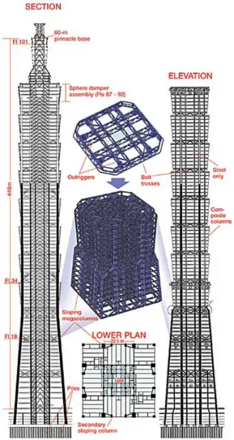
STRUCTURAL SYSTEM
- Braced core with belt trusses.
FOUNDATION
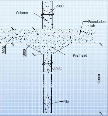
- The building is a pile through clay rich soil to bedrock 40 – 60 m below.
- The plies are topped by a foundation slab which is 3m thick at the edges and up to 5m thick under the largest of columns.
- There are a total of 380 1.5m dia. Tower piles.
COLUMN SYSTEM
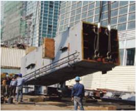
Photos of Site during Construction
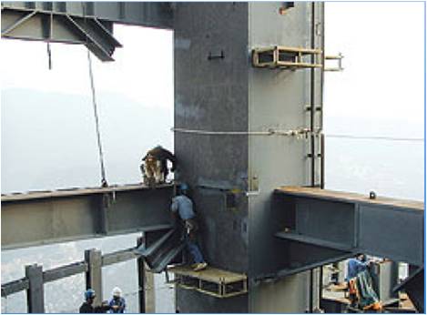
- Gravity loads are carried vertically by a variety of columns.
- Within the core, sixteen columns are located at the crossing points of four lines of bracing in each direction.
- The columns are box sections constructed of steel plates, filled with concrete for added strength as well as stiffness till the 62nd floor.
- On the perimeter, up to the 26th floor, each of the four building faces has two ‘supercolumns,’ two ‘sub-super-columns,’ and two corner columns.
- Each face of the perimeter above the 26th floor has the two ‘super-columns’ continue upward.
- The ‘super-columns’ and ‘sub-super-columns’ are steel box sections, filled with 10,000 psi (M70) high performance concrete on lower floors for strength and stiffness up to the 62nd floor.
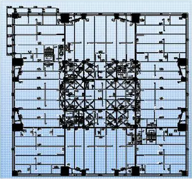
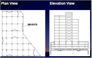
TYPICAL PLAN UP TO 26TH STOREY
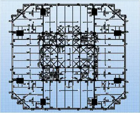
TYPICAL PLAN FROM 27TH TO 91ST STOREY
LATERAL LOADING SYSTEM
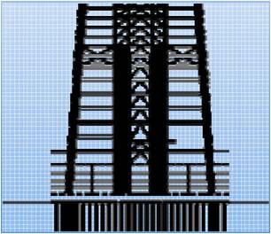
For additional core stiffness, the lowest floors from basement to the 8th floor have concrete shear walls cast between core columns in addition to diagonal braces.
- The most of the lateral loads will be resisted by a combination of braced cores, cantilevers from the core to the perimeter, the super columns and the Special moment resisting frame (SMRF).
- The cantilevers (horizontal trussed from the core to the perimeter) occur at 11 levels in the structure. 5 of them are double storey high and the rest single storey.
- 16 of these members occur on each of such floors.
- The balance of perimeter framing is a sloping Special Moment Resisting Frame (SMRF), a rigidly-connected grid of stiff beams and H shape columns which follows the tower’s exterior wall slope down each 8 story module.
- At each setback level, gravity load is transferred to ‘super-columns’ through a story-high diagonalized truss in the plane of the SMRF.
- Above the 26th floor, only two exterior super-columns continue to rise up to the 91st floor, so the SMRF consists of 600 mm deep steel wide flange beams and columns, with columns sized to be significantly stronger than beams for stability in the event of beam yielding.
- Each 7-story of SMRF is carried by a story-high truss to transfer gravity and cantilever forces to the super-columns, and to handle the greater story stiffness of the core at cantilever floors.
FLOOR SLAB (STRUCTURAL DIAPHRAGMS)
- Slabs are composite in nature and are typically 13.5 cms thick.
CORE
- Within the core, sixteen columns are located at the crossing points of four lines of bracing in each direction.
DAMPING SYSTEMS
- The main objective of such a system is to supplement the structures damping to dissipate energy and to control undesired structural vibrations.
- A common approach is to add friction or viscous damping to the joints of the buildings to stabilize the structural vibration.
- A large number of dampers may be needed in order to achieve effective damping when the movements of the joints are not sufficient to contribute to energy absorption.
ENERGY SINK DAMPING SYSTEMS
- These are one of the latest damping systems available – called Tuned Mass Damper.
- These take excess energy away from the primary structure.
TUNED MASS DAMPERS
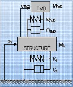
- A TMD is a passive damping system, which consists of a spring, a viscous damping device, and a secondary mass attached to the vibrating structure.
- By varying the characteristics of the TMD system, an opportunity is given to control the vibration of the primary structure and to dissipate energy in the viscous element of the TMD.
TMD USED IN TAIPEI 101
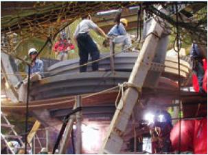
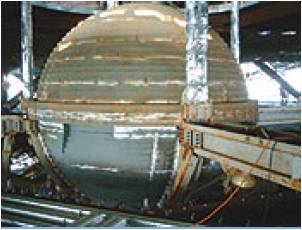
- The Taipei 101 uses a 800 ton TMD which occupy 5 of its upper floors (87 – 91).
- The ball is assembled on site in layers of 12.5-cm-thick steel plate. It is welded to a steel cradle suspended from level 92 by 3” cables, in 4 sets of 2 each.
- Eight primary hydraulic pistons, each about 2 m long, grip the cradle to dissipate dynamic energy as heat.
- A roughly 60-cm-dia pin projecting from the underside of the ball limits its movement to about 1 m even during times of the strongest lateral forces.
- The 60m high spire at the top has 2 smaller ‘flat’ dampers to support it.
STRUCTURAL INNOVATIONS IN OTHER TAIPEI BUIDINGS
- The structural systems used in Taipei 101 draw a lot from other buildings in the Taipei region.
- They can generally be classified into 2 types
a) Hysteretic Dampers
– Triangular Added stiffness and damping damper (TADAS)
– Reinforced ADAS damper (RADAS)
– Buckling Restrained Braces (BRB)
– Low Yield Steel Shear Panel (LYSSP)
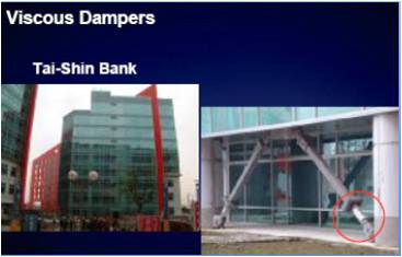
b) Velocity Dampers
– Visco – Elastic dampers (VE)
– Viscous Dampers (VD)
– Viscous Damping Walls (VDW)
- Currently, there have been more applications using viscous dampers than other velocity type dampers.
- This may be due to the facts that the design procedure for implementing the viscous damper is relatively simpler and the analytical model is available in the popular computational tools such as SAP2000 and ETABS.
this was definitely so
this was definitely so helpful !!!
thank you so much !!
where i can find all about
where i can find all about structural dimensions of this building??
So informative….
So informative….
PLease include references of
PLease include references of people who have contributed to such a beautiful article so that their work is ackowledged. ALso please include the date of posting the article if possible.
Thank you.
GOOD CASE STUDY
GOOD CASE STUDY
Hi…. amazing case study.. I
Hi…. amazing case study.. I have finished mine. But I don’t know where to find drawings (detailed) … Can u tell me, where did you find your’s?
Thankss a lot.
THIS CASE STUDY IS VERY
THIS CASE STUDY IS VERY HELPFUL,GREAT WORK
I am final year civil engg.
I am final year civil engg. student and i am doing my project on metallic damper.Can you please tell me the practical application of metallic damper? Thank you.
what is the problem that
what is the problem that faces during the construction process??
looks very nice, helpful and
looks very nice, helpful and fascinating information.
thanks