LIFTS & STAIRWAYS
Vertical Circulation
Today’s contemporary context calls for optimum intelligent usage of space. This requires construction of high rise buildings. in such buildings connectivity within the building and from outside world is of prime important. This is what gives height to a building and helps it to rise up.
Staircase/ Elevators function as primary way of connecting to various spaces in low and mid-rise buildings.
Whereas lifts/ elevators make it possible to reach the highest storey. In high rise building as soon as possible.
These sources of connectivity also help in evacuating the building as soon as possible in case of emergency.
HISTORY
- The first reference to an elevator is in the works of VITRUVIUS, who reports that ARCHIMEDES (287 B.C. – 212 B.C.) probably built his first elevator as early as 236 B.C. In 17th century the prototype of elevator was located in the buildings of England and France.
- The ancient and medieval elevators used a drive system based on hoist. The invention of another type of system based on the screw driver led to the invention of modern day elevator.
- The first screw driver lift was devised by Ivan Kulibin and installed in Winter Palace in 1793 and another one was installed later in Arkhangelskoye near Moscow.
- In 1823 “ascending room” made it’s debut in London.
- In mid 1800 there were many types of crude elevators that carried load. It used water pressure into the plunger to raise or lower the lift; but this technique was not feasible for tall buildings.
- Henry Waterman of New York is credited with “standing rope control” for an elevator in 1850.
- In 1852 Elisha Otis introduced the safety elevator which prevented the fall of cab if the cable broke. This design was somewhat similar to the deigns used today. A governor device engages knurled roller(s), locking the elevator to its guides should the elevator descend at excessive speed. He demonstrated it at the New York exposition in the Crystal Palace in a dramatic, death-defying presentation in 1854.
- In 1874, J.W. Meaker patented a method which permitted elevator doors to open and close safely. U.S. Patent 147,853
- The first electric elevator was built by Werner von Siemens in 1880. The safety and speed of electric elevators were significantly enhanced by Frank Sprague. The inventor Anton Freissler developed the ideas of von Siemens and built up a successful enterprise in Austria-Hungary.
- In 1929, Clarence Conrad Crispen, with Inclinator Company of America, created the first residential elevator. Crispen also invented the first inclined stairlift.
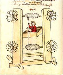
Elevator design by the German engineer,Konrad Kyeser (1405)
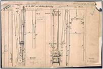
Elisha Otis’ elevator patent drawing, 15 January 1861.
TYPES OF ELEVATORS
CLASSIFICATION BASED ON 8 BROAD CATEGORIES:
- Elevator safety: Pneumatic vacuum elevator
Cable borne elevator
Hydraulic elevator
Mine shaft elevator
- Usage: Residential elevator
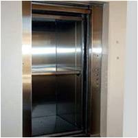
Passenger elevator
Freight elevator
Stage elevators
Vehicle elevator
Boat elevator
Aircraft elevator
Limited use elevator
Dumbwaiter
Paternoster
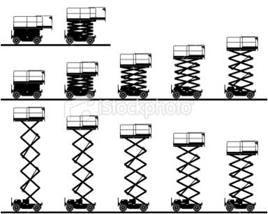
Scissor elevator
Rack and Pinion elevator
Belt elevators
- Elevator hoist mechanism: Traction elevators – Geared and non geared traction elevators
Hydraulic elevators
Climbing elevators
- Machine room: Elevator with machine rooms
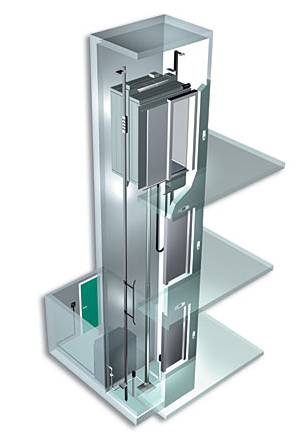
Elevators without machine rooms (MRL)
- Double deck elevator
- Panoramic view elevators
- Capsule elevator
- Regenerative elevator
ELEVATOR SAFETY
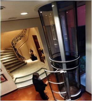
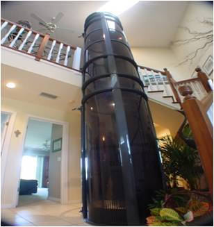
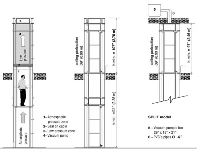
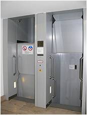
- Pneumatic or “vacuum” elevators operate without cables and are easier to install as their housing comprises of pre-fabricated sections which are considerably narrower than conventional lift-shaft and often provide the user a 360 degree view.
- Cable-borne elevators are extremely safe. Only 1 in 12 million of elevator rides results in anomaly.
- Hydraulic elevators, prior to code change in 1972, were subject to a possible catastrophic failure. Therefore “life jacket” is used which clamps the cylinder in case of excessive downward speed. Cylinder are also replaced from time to time. PVC casing/liners are used around the cylinder to prevent hydraulic oil leaks.
- Mine shaft elevators- safety testing of mine shaft elevator rails is routinely undertaken. The method involves destructive testing of a segment of the cable. Data about elasticity, load, and other factors is compiled to determine whether or not the entire rail is safe to use.

USAGE OF ELEVATORS
- Passenger elevator is designed to move people between floors of a building. Their capacity is related to available floor space. Upto 8-10 floors these operate at 1m/s or 200 ft/min and above 10 floors the speed starts at 2.5 m/s (500ft/s) to 10 m/s(2000ft/s).
There are some types of passenger elevators:-
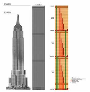
Skylobbies- The former World Trade Center’s twin towers used skylobbies located on 44th and 78 th floor of each tower.
Express elevators- An express elevator does not serve all floors. For example, it moves between the ground floor and a sky lobby, or it moves from the ground floor or a skylobby to a range of floors, skipping floors in between.
These are especially popular in eastern Asia.
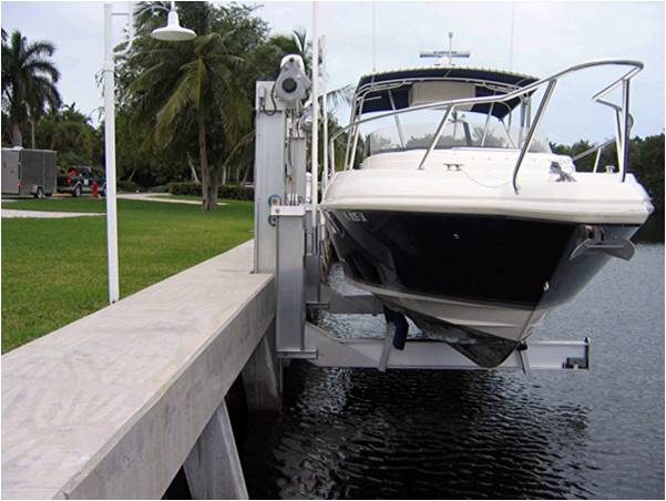
- Boat elevators in some smaller canals, boats and small ships can pass between different levels of a canal with a boat lift rather than through a canal lock.
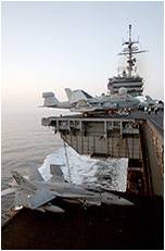
- Aircraft elevatoron aircraft carriers, elevators carry aircraft between the flight deck and the hangar deck for operations or repairs. These elevators are designed for much greater capacity than other elevators, up to 200,000 pounds (90 tones) of aircraft and equipment. Smaller elevators lift munitions to the flight deck from magazines deep inside the ship.On some passenger double-deck aircraft such as the Boeing 747, Lockheed L-1011 or other wide body aircraft, lifts transport flight attendants and food and beverage trolleys from lower deck galleys to upper passenger carrying decks.
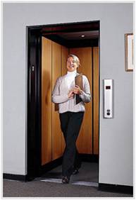
- Limited use/Limited application elevator is a special purpose passenger elevator used infrequently, and which is exempt from many commercial regulations and accommodations. For example, a LU/LA is primarily meant to be handicapped accessible, and there might only be room for a single wheelchair and a standing passenger.
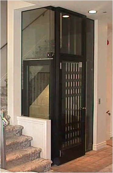
- Residential elevators They may have unique design characteristics suited for home furnishings, such as hinged wooden shaft-access doors rather than the typical metal sliding doors of commercial elevators, but safety systems such as locks on shaft access doors, fall arrestors, and emergency phones must still be present in the event of malfunction.
- Dumbwaiter Dumbwaiters are small freight elevators that are intended to carry food rather than passengers. They often link kitchens with rooms on other floors.
- Scissor elevator is yet another type of lift. As most of these lifts are self-contained, these lifts can be easily moved to where they are needed.
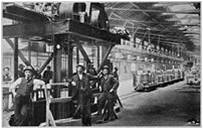
- Paternoster is a constantly moving chain of boxes. A similar concept, called the manlift or humanlift, moves only a small platform, which the rider mounts while using a handhold and was once seen in multi-story industrial plants.
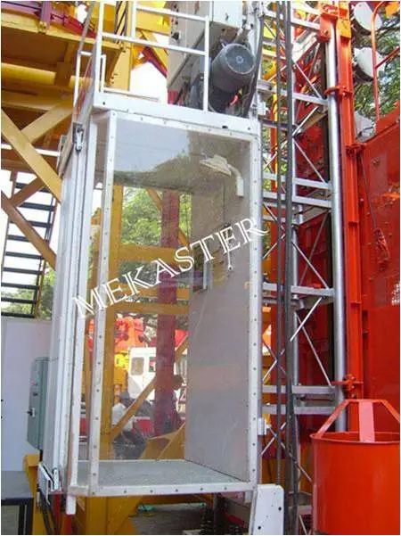
- Rack and pinion lift is another type of lift. This lifts are simpler in construction, but noisy and slow. They are nonetheless the most used type of lift for buildings under construction (to move materials and tools up and down).
- Material transport and belt elevator are used for material transport. It generally consists of an inclined plane on which a conveyor belt runs. These elevators are often used in industrial and agricultural applications.
![]()
- Stage elevators are typically powered by hydraulics, that are used to lift entire sections of a theater stage. For example, Radio City Music Hall has four such lifts: an “orchestra lift” that covers a large area of the stage, and three smaller lifts near the rear of the stage.
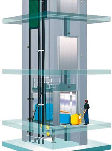
- Freight elevators are specialized elevators from 1905 for lifting narrow gauge railroad cars between a railroad freight house and the Chicago Tunnel Company tracks below. Freight elevator are generally designed to carry load whereas some allow dual use through the use of an inconspicuous riser. Freight elevators are typically larger and capable of carrying heavier loads than a passenger elevator, generally from 2,300 to 4,500 kg. Freight elevators may have manually operated doors, and often have rugged interior finishes to prevent damage while loading and unloading. Although hydraulic freight elevators exist, electric elevators are more energy efficient for the work of freight lifting.
ELEVATOR HOIST MECHANISM
- Traction elevators- Geared traction machines are driven by AC or DC electric motors. Geared machines use worm gears to control mechanical movement of elevator cars by “rolling” steel hoist ropes over a drive sheave which is attached to a gearbox driven by a high speed motor. These machines are generally the best option for basement or overhead traction use for speeds up to 500 ft/min (2.5 m/s).
-Gearless traction machines are low speed (low RPM), high torque electric motors powered either by AC or DC. Gearless traction elevators can reach speeds of up to 2,000 ft/min (10 m/s), or even higher. A brake is mounted between the motor and drive sheave (or gearbox) to hold the elevator stationary at a floor. This brake is usually an external drum type and is actuated by spring force and held open electrically; a power failure will cause the brake to engage and prevent the elevator from falling.
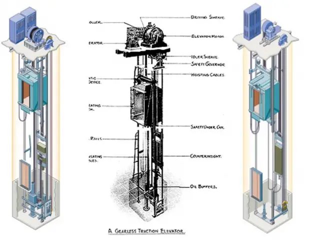
GEARLESS GEARED
Hydraulic elevators
- Conventional hydraulic elevators. They use an underground cylinder, are quite common for low level buildings with 2-5 floors (sometimes but seldom up to 6-8 floors), and have speeds of up to 200 feet/minute (1 meter/second).
- Holeless hydraulic elevators were developed in the 1970s, and use a pair of above ground cylinders, which makes it practical for environmentally or cost sensitive buildings with 2, 3, or 4 floors.
- Roped hydraulic elevators use both above ground cylinders and a rope system, which combines the reliability of inground hydraulic with the versatility of holeless hydraulic, even though they can serve up to 8-10 floors.
Conventional Hydraulic Elevator
Roped Hydraulic Elevator
Holeless Hydraulic Elevator
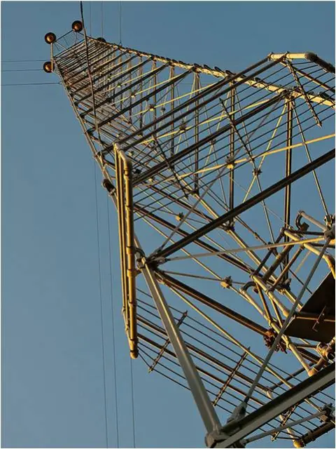
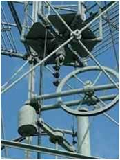
- Climbing elevators A climbing elevator is a self-ascending elevator with its own propulsion. The propulsion can be done by an electric or a combustion engine. Climbing elevators are used in guyed masts or towers, in order to make easy access to parts of these constructions, such as flight safety lamps for maintenance. An example would be the Moonlight towers in Austin, Texas, where the elevator holds only one person and equipment for maintenance.
COMPARATIVE STUDY OF M.R.L AND ELEVATORS WITH MACHINE ROOMS
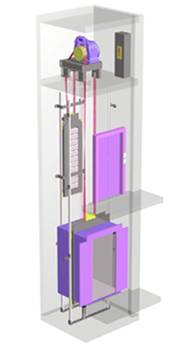
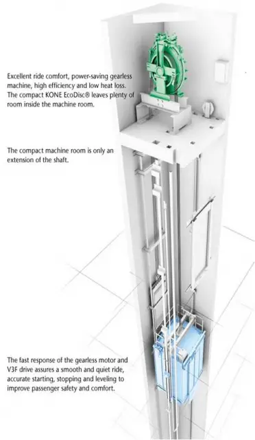
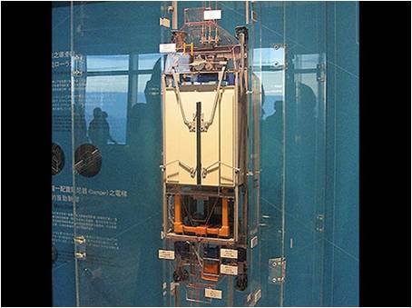
Machine room-less elevators are designed so that most of its components fit within the shaft containing the elevator car; and a small cabinet houses the elevator controller. Other than the machinery being in the hoistway, the equipment is similar to a normal traction elevator.This new design was first developed by Kone in 1996.
Benefits
- Creates more usable space
- Use less energy (70-80% less than hydraulic elevators)
- Uses no oil
- All components are above ground similar to roped hydraulic type elevators (this takes away the environmental concern that was created by the hydraulic cylinder on direct hydraulic type elevators being stored underground)
- Slightly lower cost than other elevators
- Can operate at faster speeds than hydraulics but not normal traction units
Detriments
- Equipment can be harder to service and maintain.
- No code has been approved for the installation of Residential elevator Equipment.
Facts
- Noise level is at 50-55 dBA (A-weighted decibels), which can be lower than some but not all types of elevators
- Usually used for low-rise to mid-rise buildings
- The motor mechanism is placed in the hoistway itself
- The US was slow to accept the commercial MRL Elevator because of codes
- National and local building codes did not address elevators without machine rooms.
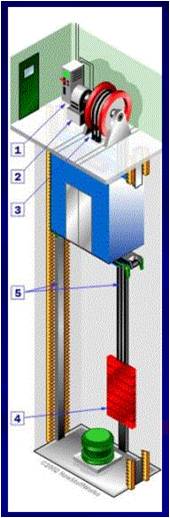
Elevators with machine-rooms are designed keeping in mind that the machine (the hoist mechanism), is kept in a separate floor while only the lift car moves in the shaft. This traditional design may have a machine room above or below the shaft. It is better not to have any other machines in the machine room apart from that of the lift, from safety point of view.
Benefits
- Traditional technology
- Has more space in the shaft for easy installation of lift
- Easy to install and takes lesser time to be installed
- Easy to service and maintain as machines are easily accessible
- Has numerous options for speed
- Widely used
- Has the option of placing machine room above or below the car
- Comply with all the codes country-wide
Detriments
- Environmental concerns related to use of oils in hoist mechanism due to leakages
- slightly higher cost than M.R.Ls.
- Can service all types of buildings
- Consumes more space
- Consumes more energy
Facts
- Noise level can be as high as 120-160 dBA
- Can be used in all types of buildings
- The motor-mechanism can be placed above or below the car
- Traditional technology which has been improved with passage of time
- Has codes that comply with it’s installation and maintenance
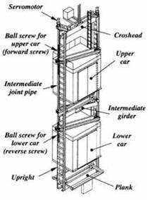
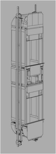
DOUBLE DECK ELEVATORS
Double-deck elevators are designed with two elevator cars that are attached, one on top of the other. This allows passengers on two consecutive floors to be able to use the elevator simultaneously, significantly increasing the passenger capacity of an elevator shaft. The elevator serving even floors is actually on top of the elevator serving odd floors in the same lift shaft. When a passenger disembarks from the even-floor-serving elevator at level 30, for instance, the passengers in the odd-floor-serving elevator beneath it are kept waiting until the elevator doors above close. Architecturally, this is important, as double-deck elevators occupy less building core space than traditional single-deck elevators do for the same level of traffic. In skyscrapers, this allows for much more efficient use of space, as the floor area required by elevators tends to be quite significant.
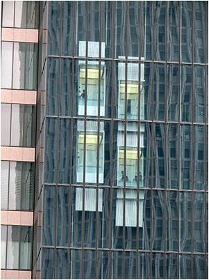
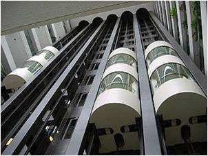
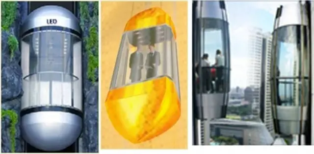
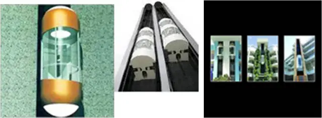
PANORAMIC VIEW ELEVATOR
Panoramic elevators, designed for their view, are usually installed on the exterior face of the building or in the lobby and are specially designed to add a dramatic element to the architectural design of the building thus giving the building an impression of elegance and comfort.
Salient Features
» Really attractive and can be called the ornaments of a building for they enhance its beauty and bring life into it » Speed – upto 2mps
» Can accommodate from 4 persons to 16 persons » Needs specialized knowledge and state of the art technology » Different options pertaining to their design are available » Different customized options for bottom, roofs and cabin exteriors.
» Traction machine based » Includes all latest available passenger safeties » Optional Glass doors give capsule lifts a world-class look.
Factors responsible for increase of application of panoramic elevators:
» Stylish – Architectural conception in combination with complication of modern technology of elevator.
» Commercial benefit – Strategically correctly located, a panoramic elevator attracts business, by promoting the status of the building in the eyes of visitors and clients through an external attractiveness and absence of discomfort which may exist in a normal closed passenger elevator.
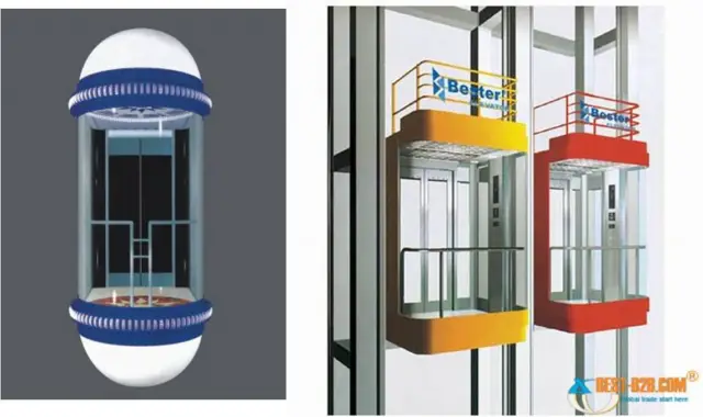
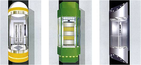
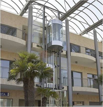
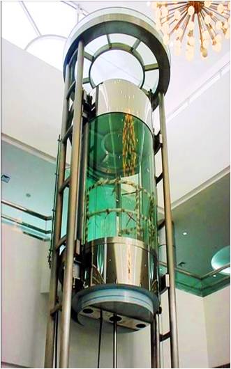
CAPSULE ELEVATORS
Capsule elevators give an additional eye catching look to a modern building and act as architectural highlights of the buildings. They act like the ornaments of a building for they enhance the beauty and bring life in it. We provide capsule elevators for Hotels, Apartments, shopping malls etc.
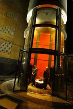
Capsule Elevator is essentially installed at a place where elevation of building is to be enhanced with display of moving lift and passenger is provided with panoramic view of surroundings. Capsule elevator normally comes in 5 and 3 Glass panel. Capsule Elevator is normally preferred in shopping malls (to give view of items displayed), 5 star hotels (to provide lobby view) and high rise residential buildings.
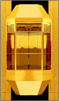
Capsule Elevators act as Architectural highlights on prestigious buildings. They can be called the ornaments of a building as they enhance its beauty and bring life into it. Its design, features and infinite options add its optimum travel comfort. It has aesthetically attractive interiors with large glass viewing panel.
HOW GREEN IS YOUR ELEVATOR
- The pressure is on today, as never before, for organizations to show their green credentials.
- With lifts, as with any product in common use in a commercial or domestic environment, the potential environmental impact is likely to have implications on both the manufacturer and the operator. Equally, consideration must be given to each stage of the lift’s life, from initial design and manufacture, through maintenance to eventual disposal.
Compliance
- The volume and range of legislation impacting directly or indirectly on lift operation increases every year.
- These regulations defined and increase the controls that must be put in place to dispose of Hazardous Waste Materials, including registration of the producers site(s) with the Environment Agency
- One way of controlling this is by ensuring effective compliance.
- It relates to a producer’s environmental policies, planning, systems and procedures, checking and review: in this way it formalizes the way in which a company meets its legal obligations regarding environmental compliance.
Building performance
- Another regulation which impacts indirectly on lift performance relates to the energy efficiency of new buildings, setting stiff targets for carbon reduction.
- The Government has also increased energy efficiency standards for new buildings through an amendment to the Building Codes.
- As a result, pressure for change is increasing from the end-user community, who face parallel regulatory pressures to improve their energy performance. For, critically, not only does this reduce any harmful impact on the environment but also delivers cost benefits to both the user and manufacturer communities.
Product design
- There is no doubt that manufacturers have recognized this and are playing their full part in addressing environmental concerns. As a result, today’s passenger and goods lifts are far more energy efficient than their counterparts a decade ago.
- The evolution of machine room-less lift technology offers a particularly striking example here.
- And in the latest designs this is achieved without compromising the level of robustness or ride quality needed in hard-working commercial environments. Further, compact gearless machinery helps reduce noise levels.
- The imperative to go green goes beyond new lift provision however. It is equally important to ensure that existing lifts contribute to the overall energy performance improvement of the building as a whole.
- New technologies also impact positively on the manufacturing process. For example, the latest modular lift and machine room-less lift designs incorporate far fewer components, so improving production efficiencies as well as substantially cutting installation times.
Ease of maintenance
- Once in use, a lift must be maintained properly if it is to continue to operate in the most efficient way throughout its lifetime.
- It is true that ensuring disruption is kept to a minimum is important to ensure business continuity, yet service quality also has wider implications. For example, one advantage of using locally-based engineers is that the length of each journey to and from the customer will be minimized, so reducing fuel consumption and CO2 emissions.
- Similarly, it is important for such service support to be able to manage the controlled disposal and recycling of waste materials such as used hydraulic oils.
- For the lift operator and service provider alike, there is much that can be done to ensure lifts operate at optimum efficiency.
REGENERATIVE ELEVATORS
To meet the challenge on energy savings, lifts are being built to last for a life-cycle extending beyond 20 years time. It incorporates energy-saving solutions that keep the total cost of ownership low while reducing the ecological footprint of the building.
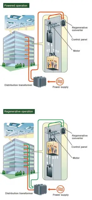
One of the latest technological developments in elevator is the regenerating system, one that focuses on recovering braking energy and converting it into electricity. Therefore, this would save energy and reduce the carbon footprint, and also improve performance, safety and comfort.
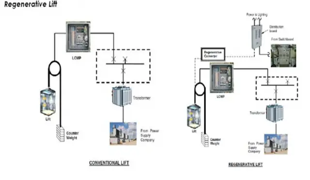
- Cost Saving for Regenerative Lifts
- Regenerative lifts generally lower overall building operating costs and achieve significant annual savings for
- building owners year-after-year during the whole life of the lifts. The amount of energy savings from
- regeneration depends on various system parameters and configurations such as car load, speed, traveling
- distance and system efficiency.
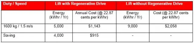
Advantages and Disadvantages of Regenerative Lifts
- Notably, the advantages of the application of regenerative lifts have outweighed the disadvantages.
- Regenerative lifts have the following advantages:
- Use up to 50% less energy than a traction
- About 50% of the energy used by the lift can be recovered by their regenerative system
- Recovers excess braking energy from the elevator and converts it for use e.g. in lighting the building
- Produces clean and safe energy that does not damage the network
- Energy saving: 4000 kWh/year compared to a non-regenerative drive for the above example
- Carbon footprint reduction: 2000kg CO2/year compared to a non-regenerative drive for the above example.
UNIQUE ELEVATOR INSTALLATION AROUND THE WORLD
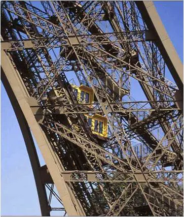
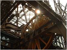
- EIFFEL TOWER– The Eiffel Tower has Otis double-deck elevators built into the legs of the tower, serving the ground level to the first and second levels. Even though the shaft runs diagonally upwards with the contour of the tower, both the upper and lower cars remain horizontally level. The offset distance of the two cars changes throughout the journey.
- There are four elevator cars of the traditional design that run from the second level to the third level. The cars are connected to their opposite pairs (opposite in the elevator landing/hall) and use each other as the counterweight. As one car ascends from level 2, the other descends from level 3. The operations of these elevators are synchronized by a light signal in the car.
- TAIPEI 101– Double deck elevators are used in the Taipei 101 office tower. The lower deck is turned off during low-volume hours, and the upper deck can act as a single-level elevator stopping at all adjacent floors.
- A bank of express elevators stop only on the sky lobby levels (36 and 60, upper deck car), where tenants can transfer to “local” elevators.
- The high speed observation deck elevators accelerate to a world-record certified speed of 1010 meters per minute (60.6 km/h) in 16 seconds, and then it slows down for arrival with subtle air pressure sensations. The door opens after 37 seconds from the 5th floor. Special features include aerodynamic car and counterweights, and cabin pressure control to help passengers adapt smoothly to pressure changes. The downwards journey is completed at a reduced speed of 600 meters per minute, with the doors opening at the 52nd second.
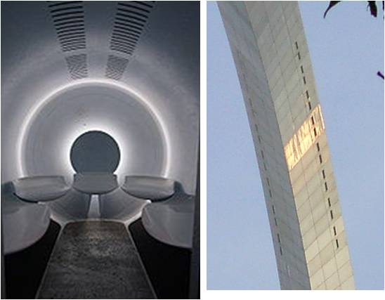
- THE GATEWAY ARCH-The Gateway Arch in St. Louis, Missouri has a unique elevator system which carries passengers from the visitors’ center underneath the Arch to the observation deck at the top of the structure.
- Called a tram or tramway .
- Passing through the doors the passengers in small groups enter a horizontal cylindrical compartment containing seats on each side and a flat floor. A number of these compartments are linked to form a train.
- There are two tramways within the Arch, one at the north end, and the other at the south end.
- The entry doors have windows, so people traveling within the Arch are able to see the interior structure of the Arch during the ride to and from the observation deck.
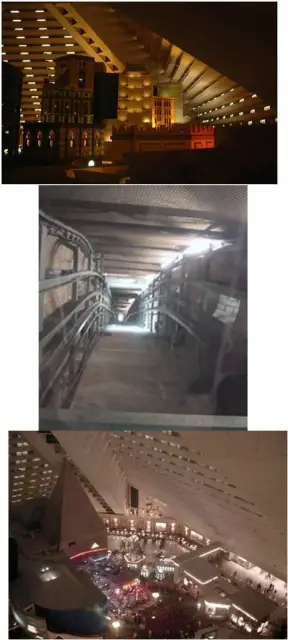
LUXOR INCLINATOR ELEVATOR– In Las Vegas, Nevada, at the Luxor Hotel, is the Inclinator. The shape of this casino is a pyramid. Therefore, the elevator travels up the side of the pyramid at a 39 degree angle. Although people refer to this “inclined elevator” as an inclinator, this is incorrect.
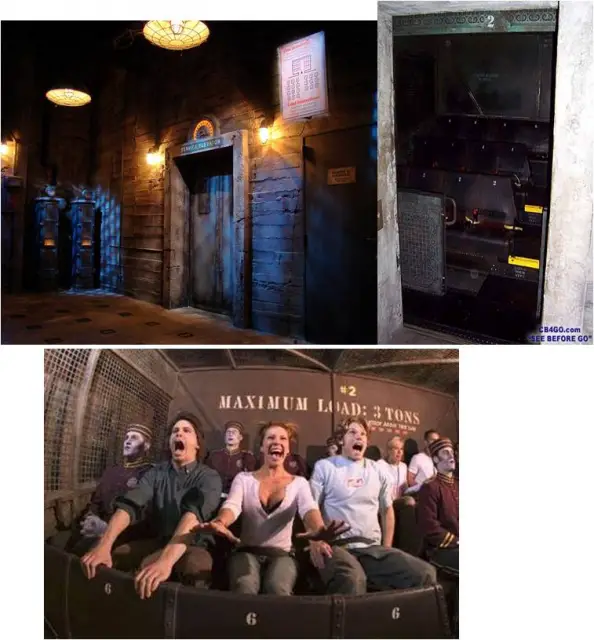
- TWILIGHT ZONE TOWER OF TERROR- The Twilight Zone Tower of Terror is the common name for a series of elevator attractions at the Disney’s Hollywood Studios park in Orlando, the Disney’s California Adventure park in Anaheim, the Walt Disney Studios Park in Paris and the Tokyo Disney Sea park in Tokyo.
- The central element of this attraction is a simulated free-fall achieved through the use of a high-speed elevator system. For safety reasons, passengers are seated and secured in their seats rather than standing.
- The doorways of the top few “floors” of the attraction are open to the outdoor environment, thus allowing passengers to look out from the top of the structure.
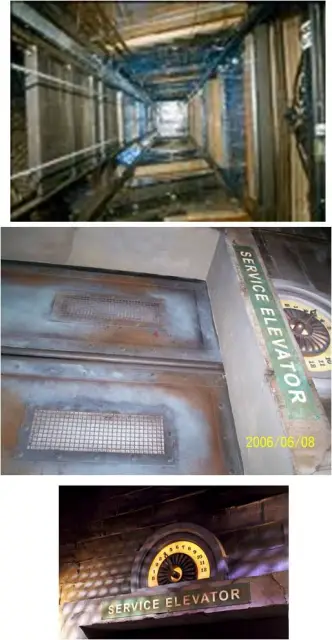
- DISNEYLAND, ANAHEIM, CALIFORNIA- Part of the Haunted Mansion attraction at Disneyland in Anaheim, California, takes place on an elevator
- The “stretching room” on the ride is actually an elevator that travels downwards, giving access to a short underground tunnel which leads to the rest of the attraction.
- The elevator has no ceiling and its shaft is decorated to look like walls of a mansion. Because there is no roof, passengers are able to see the walls of the shaft by looking up, which gives the illusion of the room stretching.
CASE 1:
Taking traffic density=4 people per 24 sq. mt.
Plot Area= 4000 sq.mt. so acc. to F.A.R.= 150 , we have total built area=6000 sq.mt.
We assume the building to have 6 floors, (ignoring the set backs on the site)
Therefore each floor plate has an area of 1000 sq.mt and reducing the 30% of wall area; we get 700 q. mt.
Using the traffic density; we have 117 people occupying the floor.
This is a commercial building with diversified as well as unified offices.
So we take traffic density to be 20% which is 25 people and since the floor height is 3.5 mts. and we have 6 floors; so we have a total height of 22.4 mts.
Taking 30 secs. as time interval; the speed comes out to be 0.75 m/s
Therefore, the no. of lifts= RT/T
(RT=round trip time; time taken by the lift to take passenger to various floors and come back to ground floor after discharging them
T= waiting interval in secs.)
=124/30= 4.4= 4 lifts are needed
Handling capacity of lifts=(300XQX100)/(TXP)
(Q=average no. of passengers in a car; T= waiting time; P= total population to be handled during peak hours=40 people in each floor)
=(300X13X100)/(30X240)
=(390000)/7200= 54%
Since there are 13 people; so the weight amounts to 884 kg.
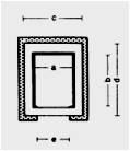
Car Dimensions=width (A)= 2000 mm
depth (B)= 1100mm
Lift Well Dimensions=width (C)=2500 mm
=depth (D)=1900 mm
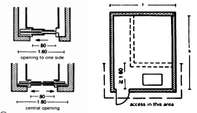
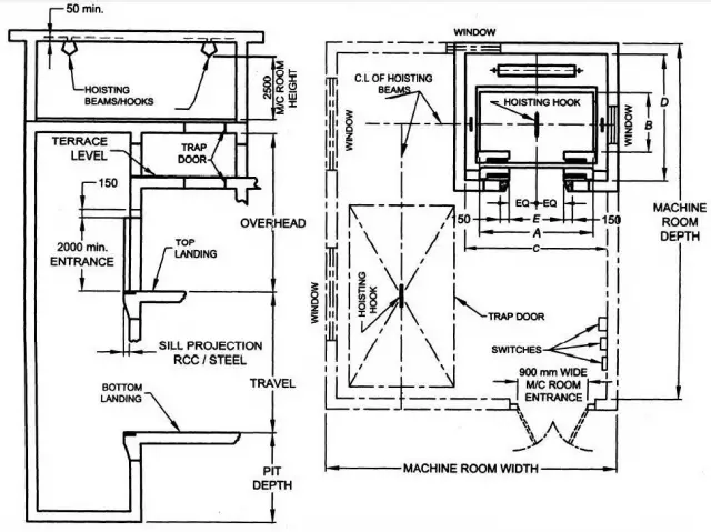
with an entrance (E) that should be min. 900 mm wide and 2000 mm high
since the preferred speed is b/w 0.7 m/s and 1.0 m/s , Therefore
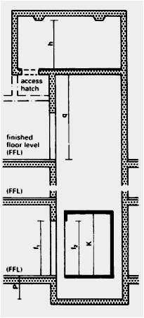
The PIT should be min. 1500 mm deep
Overhead height should be 4250 mm
Machine room depth should be= D+ 2000=3900 MM
Machine room width should be=C+1000=3500 MM
Car height is taken 2.3mts
CASE 2:
Taking traffic density =4 people per 24 sq.mt.
Plot Area= 4000 sq.mt. so acc. to F.A.R.= 150 , we have total built area=6000 sq.mt.
We assume the building to have 20 floors, (ignoring the set backs on the site)
Therefore each floor plate has an area of 300 sq.mt and reducing the 30% of wall area; we get 210 q. mt.
Using the traffic density; we have 36 people occupying the floor.
This is a commercial building with diversified as well as unified offices.
So we take traffic density to be 20% which is 10 people and since the floor height is 3.5 mts. and we have 20 floors; so we have a total height of 74 mts.
Taking 30 secs. as time interval; the speed comes out to be 2.5 m/s
Therefore, the no. of lifts= RT/T
(RT=round trip time; time taken by the lift to take passenger to various floors and come back to ground floor after discharging them
T= waiting interval in secs.)
=260/30= 8.6= 8-10 lifts are needed
Handling capacity of lifts=(300XQX100)/(TXP)
(Q=average no. of passengers in a car; T= waiting time; P= total population to be handled during peak hours=10 people in each floor)
=(300X10X100)/(30X200)
=(300000)/6000= 50%
Since there are 10 people; so the weight amounts to 680 kg.
Car Dimensions=width (A)= 1300 mm
depth (B)= 1350mm
Lift Well Dimensions=width (C)=1900 mm
=depth (D)=2100 mm
with an entrance (E) that should be min. 800 mm wide and 2000 mm high
since the preferred speed is b/w 2.0 m/s and 2.5 m/s , Therefore
The PIT should be min. 2500 mm deep
Overhead height should be 5400 mm
Machine room depth should be= D+ 2500=4600 MM
Machine room width should be=C+1500=3400 MM
Car height is taken 2.3mts
CASE 3:
Taking traffic density=4 people per 24 sq. mt.
Plot Area= 7000 sq.mt. so acc. to F.A.R.= 150 , we have total built area=10500 sq.mt.
We assume the building to have 15 floors, (ignoring the set backs on the site)
Therefore each floor plate has an area of 700 sq.mt and reducing the 30% of wall area; we get 500 q. mt.
Using the traffic density; we have 84 people occupying the floor.
This is a commercial building with diversified as well as unified offices.
So we take traffic density to be 20% which is 18 people and since the floor height is 3.5 mts. and we have 15 floors; so we have a total height of 55.7 mts.
Taking 30 secs. as time interval; the speed comes out to be 1.9 m/s
Therefore, the no. of lifts= RT/T
(RT=round trip time; time taken by the lift to take passenger to various floors and come back to ground floor after discharging them
T= waiting interval in secs.)
=210/30= 7= 7 lifts are needed
Handling capacity of lifts=(300XQX100)/(TXP)
(Q=average no. of passengers in a car; T= waiting time; P= total population to be handled during peak hours=20 people in each floor)
=(300X10X100)/(30X300)
=(300000)/9000= 33.3%
Since there are 10 people; so the weight amounts to 680 kg.
Car Dimensions=width (A)= 1300 mm
depth (B)= 1350mm
Lift Well Dimensions=width (C)=1900 mm
=depth (D)=2100 mm
with an entrance (E) that should be min. 800 mm wide and 2000 mm high
since the preferred speed is b/w 1.75 m/s and 2.0 m/s , Therefore
The PIT should be min. 2200 mm deep
Overhead height should be 5200 mm
Machine room depth should be= D+ 2500=4600 MM
Machine room width should be=C+1500=3400 MM
Car height is taken 2.3mts
CASE 4:
Taking traffic density=4 people per 24 sq. mt.
Plot Area= 7000 sq.mt. so acc. to F.A.R.= 150 , we have total built area=10500 sq.mt.
We assume the building to have 10 floors, (ignoring the set backs on the site)
Therefore each floor plate has an area of 1050 sq.mt and reducing the 30% of wall area; we get 740 q. mt.
Using the traffic density; we have 125 people occupying the floor.
This is a commercial building with diversified as well as unified offices.
So we take traffic density to be 20% which is 25 people and since the floor height is 3.5 mts. and we have 10 floors; so we have a total height of 37.2 mts.
Taking 30 secs. as time interval; the speed comes out to be 1.24 m/s
Therefore, the no. of lifts= RT/T
(RT=round trip time; time taken by the lift to take passenger to various floors and come back to ground floor after discharging them
T= waiting interval in secs.)
=160/30= 5.3= 5 lifts are needed
Handling capacity of lifts=(300XQX100)/(TXP)
(Q=average no. of passengers in a car; T= waiting time; P= total population to be handled during peak hours=25 people in each floor)
=(300X16X100)/(30X250)
=(390000)/7200= 64%
Since there are 16 people; so the weight amounts to 1088 kg.
Car Dimensions=width (A)= 2000 mm
depth (B)= 1300mm
Lift Well Dimensions=width (C)=2500 mm
=depth (D)=2100 mm
with an entrance (E) that should be min. 1000 mm wide and 2000 mm high
since the preferred speed is b/w 1.0 m/s and 1.5 m/s , Therefore
The PIT should be min. 1600 mm deep
Overhead height should be 4800 mm
Machine room depth should be= D+ 2000=4100 MM
Machine room width should be=C+1200=3700 MM
Car height is taken 2.3mts
- Lifts (BYE-LAWS)
- All floors shall be accessible for 24 hours by the lift
- Lifts provided shall not be considered as a means of escape at times of emergency.
- Grounding switch at ground floor level to enable the fire service to ground the lift in case of an emergency shall also be provided.
- The lift machine room shall be separate and no other machinery shall be installed there.
- Whenever the lift is required as per the bye-laws , provisions of atleast one lift shall be made for the wheel-chair user with the following car dimensions of the lift recommended for passenger lift for 13 persons capacity by B.I.S.
- Clear Int. Depth -1100 mm
- Clear Int. Width -2000 mm.
- Entrance Door width -910 mm
- Handrail – not less than 600 mm at 900 mm above floor level and is fixed adj. to control panel.
- The lift lobby -Inside measurement of 1800 mm by 2000 mm or more.
- The Braille signage shall be posted outside the lifts.
- The operational details of the lifts shall comply with N.B.C.
- Lift enclosures
- The walls enclosing the lift shall have a fire-resistance of not less than two hours with shafts having permanent vents at top not less than 1800 sq. m. in clear area. Lift room shall be preferably at the top of shaft and shall be separate from shaft by enclosing wall of shaft or by floor of the motor rooms.
- Landing doors in lifts shall open in ventilated or pressurized corridor or lobby and shall have fire resistance of not less than one hour.
- The no. of lifts in one lift bank shall not exceed more than 4. Shaft for fire lift in a lift bank shall be separated from each other by a brick masonry or RCC wall of fire resistance not less than 2 hour.
- If the lift shaft and lift lobby are in the core of the building; a positive pressure of not less than 2.5 mm and not more than 3 mm. w.g. by an electrically operated blower shall be maintained in the lift lobby and a positive pres. Of not less than 5 mm w.g. shall be maintained in lift shaft. The mechanism for pressurizing the lift shaft and lift lobby shall be so maintained that they shall operate automatically when automatic fire alarm operates. The mechanism shall have facility to operate manually.
- Exit from lift lobby shall be through a self-closing smoke stop door of half-hour fire resistance.
- Lift machine room shall be separate and no other machinery shall be installed therein.
- Lifts shall not normally communicate, with basement. However one lift may be permitted to reach basement levels provided the lift lobby at each basement level is pressurized and separated from rest of basement areas, by smoke actuated fire resisting door of 2 hours fire resistance.
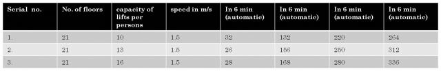
- Note 1 : For all non-residential buildings, the traffic cleared in 50 min. is considered adequate and is approved by authority. As such for calculating the no. of lifts required, the rate of the clearance of traffic in col. 9 & 10 and the population may be taken into consideration.
- Note 2: The population may be worked out on the basis of the useful carpet area which the person occupy.
- Note 3 : The population on ground and first floor may not be taken into consideration since these floors are not generally served by lifts. 0.75 m per sec equivalent to 150” per min. / 1.00 m per sec equivalent to 200” per min. / 1.5 m per sec. equivalent to 300” per min.
- Note 4 : The heights of building for lift installation i.e. the travel on the lift presumed in above statements is as below – 21 floors(64 m.)
- Service duct
- Service ducts for electrical conduits, cables etc. shall be enclosed by walls having a fire resistance of not less than two hours. Doors for inspection or access shall also have fire resistance of not less than two hours.
- If the cross sectional area exceeds 1sq. m. it shall be sealed where it passes a floor by carrying the floor through the duct. The floor within the duct shall be pierced for any service pipe or ventilation trunk and shall fit as closely as possible around any such pipe or trunk.
ELEVATORS
Lifts should be designed in such a way that they should be able to meet the increasing demand even after ten years of installation.
Average waiting time is the time between pressing the button and arrival of lift car : cycle time (s) x no. of lifts.
Transportation capacity is maximum no. of passengers it can carry within 300 seconds:
300 (s) X car load X cycle time (s) X no. of lifts
Taking traffic density to be 4 people per 24 sq. m.floor plate area= 1500sq. m. and after reducing 30% of covered area from it; we get =1050sq. m.
Therefore 176 people occupy the floor since the building comprises of individual as well as diversified office;
so we take the traffic density to be 20%; which is 35 people
Taking floor height to be 3.5 m. AND since there are 23 floors so we have a total height of 86 m.
30 seconds is the required time interval.
Therefore the speed comes out to be 2.8 m/s

Arrangement for Eight Lifts


Now;
No. of lifts =RT/T
(RT=round trip time; taken by the lift to take passengers to
various floors and come back to ground floor after discharging them
and T is waiting interval in seconds)
=250/30 =8 lifts are needed to service the building effectively.
Handling capacity of lift= (300 X Q X 100)/ (T X P) (Q=avg. no. of passengers in a car
= (300 x 15 x 100)/(30×23000) T=waiting time and P=total population
=6.5 % to be handled during peak hours)
Average energy used per cycle, in Wh
Average stand-by power of the monitored lifts (W)
Running energy consumption
- Motor efficiency : 15% lower loses than IE3 (super premium or permanent magnet synchronous motors)
- Efficiency of helical gear – 96%
- Friction losses – 5%
Stand-by energy consumption
- LED lighting (varies from 12 W with load 320 kg to 18 W with 1000kg load)
- Electric controllers – 25W
- Inverter – 20 W
- Door operator – 5 W
- Buttons and displays
The key average characteristics of these lifts are the result of the averages of the lifts installed base :
- Average motor power
- Average load
- Average rise
- Average speed
- Average number of trips per year
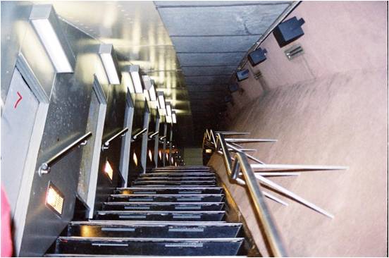
Stairways(BYE-LAWS)
- Interior staircase shall be constructed as a self-contained unit with atleast one side adjacent to an external wall and shall be completely enclosed. For buildings more than 15 m height, all staircases shall be enclosed.
- Interior stairs shall not be constructed of combustible materials (The material which either bums itself or adds heat to a fire, when tested for non-combustibility in accordance with accepted Standard )throughout.
- Assembly buildings like 2.0 m auditoria, theatres and cinemas / other buildings 1.5 m .
- A staircase shall not be arranged round a lift shaft unless the latter is entirely enclosed by a material of enclosed by a material of fire-resistance rating as that for type of construction itself. For buildings more than 15 m in height, the staircase location shall be to the satisfaction of chief fire officer, Delhi fire service.
- Hollow combustible construction shall not be permitted.
- The minimum width of internal staircase shall be 1:00 m and assembly buildings like 2.0 m auditoria, theatres and cinemas / other buildings 1.5 m .
- The minimum width of treads without nosing shall be 25 cm for an internal staircase for residential buildings. In case of other buildings the minimum tread shall be 30 cm. The treads shall be constructed and maintained in a manner to prevent slipping. Winders shall be allowed in residential buildings provided they are not at the head of a downward flight.
- The maximum height of riser shall be 19 cm in the case of residential buildings and 15 cm in case of other buildings. They shall be limited to 12 per flight.
- Handrails shall be provided with a minimum height of 90 cm from the centre of the tread.
- The minimum headroom in a passage under the landing of staircase and under the staircase shall be 2.2 m.
- For buildings more than 24 m higher, access to main staircase shall be gained through atleast half an hour fire resisting automatic closing doors placed in the enclosing walls of the staircases. It shall be a swing type door opening in the direction of the escape.
- No living space, store or rather fire risk shall open directly into the staircase or staircases.
- External exit door of staircase enclosure at ground level shall open directly to the open spaces or can be reached without passing through any door other than a door provided to form a drought lobby.
- The exit sign with arrow indicating the way to the escape route shall be provided at a height of 0.5 m from the floor level of the wall and shall be illuminated by electric light connected to corridor circuits. All exit way marking signs should be flushed with the wall and so designed that no mechanical damage shall occur to them due to moving of furniture or other heavy equipments. Further all landings of floor shall have floor indication boards indicating the number of floor as per bye-law no. 2.35. The floor indication board shall be placed on the wall immediately facing the flight of stairs and nearest to the landing. It shall be of size not less than 0.5*0.5 m.
- Wet Riser — An arrangement for fire fighting within the building by means of vertical rising mains not less than 100 mm nominal diameter with landing valves on each floor landing for fire fighting purposes and permanently charged with water from a pressurized supply.
- Individual floor shall be prominently indicated on the wall facing the staircases.
- In case of single staircase it shall be by a separate staircase. However, the second staircase may lead to the basement levels provided the same is separated at ground level by either a ventilated lobby with discharge points at two different ends or through enclosures.
- In case of single staircase it shall terminate at the ground floor level and the access to he basement shall be by a separate staircase. The second staircase may lead to basement levels provided the same is separate at ground level by ventilated lobby with discharge points to two different ends through enclosures.
- Straight flights of steps are preferred by ambulant disabled people. Treads should be approximately 300 mm deep and risers not higher than 150 mm. Steps should be of a consistent height and depth throughout the stair. Projecting nosing and open stairs should be avoided to minimize the risk of stumbling.
- Handrails should be provided to both sides of any stairway. They should be continuous and extend not less than 300 mm beyond the top and bottom step.
- For people with impaired vision, there should be a colour contrast between landing, and top and bottom steps of a flight of steps,, or the front edge of each step should have a contrasting colour.

Fire escape or External stairs
- Fire escape shall not be taken into accounting of calculating the evacuation time of a building.
- External stairs shall always be kept in sound operable conditions.
- All fire escapes shall be directly connected to the ground.
- Entrance to the fire escape shall be separate remote from the internal staircase.
- The route to the fire escape shall be free obstructions at all times, except a doorway leading to the fire escape which shall have the required fire resistance.
- Fire escape shall be constructed of non-combustible materials.
- No external staircase, used as a free escape, shall be inclined at an angle greater than 45° from the horizontal.
- Fire escape shall have straight flight not less than 75 cm. wide 25 cm. treads and riser not more than 19 cm. The number of riser shall be limited to 16 per flight.
- Handrails shall be of a height not less than 1000 mm and not more than 1200 mm. There shall be provisions of balusters with maximum gap of 150 mm.
- The use of spiral staircase shall be limited to low occupant load and to a building not exceeding 9 m in height. A spiral stair case shall be not less than 1500 mm in diameter and shall be designed to give adequate headroom.
- The access to the basement shall be separate from the main and alternative staircase providing access and exit from higher floors. Where the staircase is continuous in the case of buildings served by more than one staircase, the same shall be of enclosed type serving as a fire separation from the basement floor and higher floors.
Corridors
- The minimum width of corridor in a residential building shall be 1 m. and in all other buildings shall be 1.5 m.
- Where stairways discharge through corridors and passageways, the height of corridors and passageways shall be not less than 2.4 m.
- In case of more than one staircase of the building inter-connected by a corridor or other enclosed space, there shall be atleast one smoke stop door across the corridor or enclosed space between the doors in the enclosing walls of any two staircases.

Staircase enclosure
- The internal enclosing walls of staircase shall be of brick or R.C.C. construction having fire resistance of not less than two hours. All enclosed staircase shall have access through self-closing doors of atleast half-hour fire resistance. These shall be single swing doors opening in the direction of the escape. The door shall be fitted with check action door closers.
- The staircase enclosure on external wall of the building shall be ventilated to at atmosphere at each building.
- The permanent vent at the top equal to 5% of the cross sectional area of the enclosure and openable sashes at each floor level with area equal to 15% of the cross sectional area of the enclosure of external wall shall be provided. The roof of the shaft shall be atleast 1 m above the surrounding roof. There shall be no glazing or glass bricks in any internal enclosing wall of a staircase. if the staircase is in the core of the building and cannot be ventilated at each landing, a positive pressure of 5 mm. w.g. by an electrically operated blower/blowers shall be maintained.
- The mechanism for pressuring the staircase shaft shall be so installed that the same shall operate automatically and also with manual operation facilities, when the automatic fire alarm operates.
Horizontal exits
- The width of horizontal exit shall be same as for the exit doorways.
- A horizontal exit shall be equipped with at least one fire/smoke door of minimum 1 h fire resistance, of self-closing type. Further, it is required to have direct connectivity to the fire escape staircase for evacuation.
- Where there is a difference in level between connected areas for horizontal exits, ramps, not more than 1 in 10 m slope shall be provided; steps shall not be used.
- Doors in horizontal exits shall be open able at all times from both sides.
- Not less than two exits, as remote from each other as practicable, shall be accessible from every floor, including basement.
- Exits and ways of access thereto shall be so arranged that they are accessible in at least two different directions from every point in any open area, or from any room door.
- Any room or section with an outside door at street or grade level may have such outside door as a single exit, provided no part of the room or area is more than 15 m from the door measured along the natural path of travel. Provision of panic bars shall be provided in the exits.
Staircase at basement
- The staircase of the basements shall be of enclosed type having fire resistance of not less than two hours and shall be situated at the periphery of the basement and shall communicate with basement through a lobby provided with fire-resisting self-closing doors of half-hour fire resistance. If the travel distance exceeds 18.50 m. additional staircase at the proper places shall be provided.
- The access to the basement shall be separate from the main and alternative staircase providing access and exit from higher floors. Where the staircase is continuous in the case of buildings served by more than one staircase, the same shall be of enclosed type serving as a fire separation from the basement floor and higher floors.
- In dimensioning and design of flight of stairs, the function and purpose of staircase is of primary importance.
- From physiological point of view, the best use of climbing effort is with an angle of incline of 30 degrees.
- For the optimum rise which consumes least amount of energy; the following
- formula can be applied: 2R+T=63 cms. (one stride).


Nosing is not necessary for external staircase as per the bye-laws 
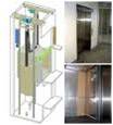
ANTRIKSH BHAWAN- LIFT WELL AND MACHINE ROOM


Generator room


Lift shafts

Lift controls


CASE STUDY: AMBIENCE MALL, GURGAON
- Floor serviced- 6 (2 basement + 4 floors)
- Type of lift- Panoramic capsule lift
- Speed- 1.0 mps
- Otis- Cable Borne Elevator System
- Machine room on top
- No. of lifts- 3 Lift Banks Containing 2 Lifts in each bank
- Onamental purpose
- Capacity- 15 ppl/ 1000kgs
After consulting N.B.C
Lift Well Dimensions=width (C)=2500 mm
=depth (D)=2100mm
with an entrance (E) that should be min. 1000 mm wide and 2000 mm high
since the preferred speed is b/w 1.0 m/s and 1.5 m/s , Therefore
The PIT should be min. 1600 mm deep
Overhead height should be 4800 mm
Machine room depth should be= D+2000=4100 MM
Machine room width should be=C+1200=3700 MM
Car height is taken 2.3mts


Leave a Reply
You must be logged in to post a comment.